
A Trusted Lifetime Partner for Carbon Storage Surveillance
Achieve total subsurface insight with a comprehensive mapping and surveillance toolbox from a trusted name in geophysics to enable safe, efficient, and cost-effective monitoring for Carbon Capture and Storage (CCS) sites.
The Ultimate Carbon Storage Toolkit
Overcome the challenges of carbon storage mapping, monitoring and verification (MMV) with a comprehensive, versatile suite of tools tailored to your carbon storage needs.
Our flexible 4D geophysical monitoring solutions empower customers to balance their CCS monitoring needs with geophysical and operational obstacles and costs.
- Ultra-High Resolution 3D (UHR3D) Seismic: Get an unrivaled image of the overburden and plume at the detail you need.
- Advanced Streamer Seismic
Multi-sensor broadband seismic data acquisition, imaging, and precise characterization for cost-effective CCS planning and monitoring - Ocean Bottom Nodes (OBN): Combine resolution with insight and repeatability with a combination of high-resolution seismic sources and ocean bottom sensors.
- Distributed Acoustic Sensing (DAS) / Vertical Seismic Profile (VSP): Vertical-in-well fiber optics will get you as close as possible to the target for on-demand repeatability.
Bringing Cutting-Edge Seismic Acquisition to CCS
TGS is actively testing a variety of cost-effective seismic acquisition and node-based technologies to enhance subsurface imaging efficiencies.
Our Ultra-High Resolution 3D (UHR3D) imaging technology, also known as extended high-resolution (XHR), can provide accurate subsurface imaging of carbon storage sites for initial site identification and ongoing 4D monitoring.
Combined with ocean bottom node (OBN)-based solutions, UHR3D seismic can also provide innovative, repeatable and cost-effective solutions to monitor carbon storage reservoirs.

Improved CCS Subsurface Insight with Advanced Ocean Bottom Node Technology
We are powering the future of carbon sequestration. Our recent collaboration at the Sleipner field utilizes UHR3D ultra-high resolution seismic imaging technology combined with ocean bottom nodes to vividly image the saline aquifer of the Utsira Formation on Sleipner East and the CO2 stored within.

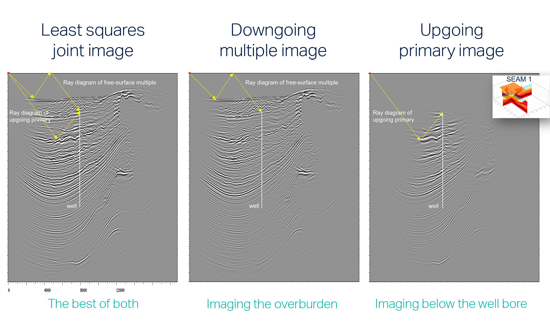
DAS least-squares joint imaging of multiples and primaries (synthetic example SEAM 1 model). When utilizing sea surface down-going multiples the imaging area around a vertical optical fiber increases (5 km radius here). Local geology determines area imaged, in most cases, it will image the area of a CO2 plume after 25-year injection. Click on the image to enlarge.
DAS / VSP: Leveraging Fiber Optic Technology
TGS seismic imaging supports cost-effective 4D CO2 “in well” or "on seafloor” fibre optic monitoring solutions (DAS-VSP). The resultant time-staggered datasets can cover the 4D needs for the injected CO2 plume for two decades or more, reducing the cost of the overall monitoring program.
- Reduces acquisition risk and delivers a robust 4D solution
- Low cost and effective for life of well solution
- Technology is already widely adopted within oil and gas
Speak to a Specialist
Got a question? We're here to help. Drop us a line and provide your contact details so one of our energy data experts can get in touch with you.