Aker BP’s Digital Foundation Project
Aker BP explores for and produces oil and gas on the Norwegian continental shelf. In production the company is one of the largest independent listed oil companies in Europe.
Brownfield assets built over more than 40 years
Aker BP operate six assets: Alvheim, Ivar Aasen, Skarv, Edvard Grieg, Ula and Valhall and is a partner in Johan Sverdrup.
-

Valhall
Production start: 1982 -
 UlaProduction start: 1986
 -
 AlvheimProduction start: 2008
 -
 SkarvProduction start: 2012
 -
 Ivar AasenProduction start: 2016
 -
 Edward GriegProduction start: 2015
The first one built in 1982 and the last to finalize will be Yggdrasil in 2027, the seventh asset. With Yggdrasil, extensive new infrastructure is planned, including three platforms, nine subsea templates, new pipelines for oil and gas export and power from shore. The entire Yggdrasil area will be remotely operated from an integrated operations centre and control room onshore in Stavanger.
Enterprise-wide data collection and management of plant data
Aker BP initiated an enterprise-wide digitalization effort in 2018 with a mission to create end-to-end solutions from OT to IT for SAS (Safety& Automation System) data across all assets. Early experience in the project revealed the need for robust, secure and reliable solutions. Hence, a set of focus areas for the project was defined:
- Data quality
- Robust change processes
- Automatic flow of changes from the OT systems
- Information management
- Standardized solutions across all assets
- Use established products with lifecycle management
OPC UA was identified as the technology that could deliver on the focus areas, especially since relevant implementation was also available in mature vendor products. Equinor’s Johan Sverdrup project finalized in 2019 the upstream O&G industry’s most extensive OPC UA installation to this date. With Aker BP’s close relation to this asset, it provided confidence that OPC UA in O&G was mature for enterprise scale-out.
New solutions, based on the different SAS vendors solutions, were implemented for each asset to allow for streaming of OPC UA data from SAS to IT. The solutions were selected to minimize risk as it was considered that each vendor knows their system best with regards to how to extract the data and make it available in an OPC UA server. In addition, these solutions were available as a standard product with a life cycle management and continuous development.
Now the core goal was to bring all data together from all assets, get a standardized context in place, independent of plant level suppliers, and feed these data to the enterprise IT applications. With a standardized context, we mean the efforts of assuring all data become normalized, so that a piece of equipment with its sensors, like a valve, appears the same way to enterprise users, independent on time commissioned, commission engineer, equipment vendor and protocol used for the original valve installation.
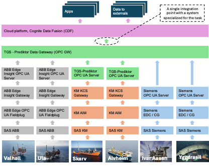
The first take on this was to collect all data with OPCUA, assure contextualization of the data per asset, but not necessarily the same information model, and then feed the enterprise cloud system with the data and leave the data normalization task to the cloud system. The overall architecture looked like this with colour coded to indicate different vendors:
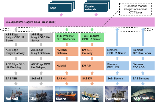
We did experience some challenges with this architecture though. With continuous changes in the many different layers of OT systems, we needed automated system workflows to cope with such changes as they rippled through the layers. We saw that the normalization that needed to happen in the IT cloud layer was a challenge because of these dynamics. There are several root causes for this, among them, different organizational resources need to work together across plant OT and enterprise IT department layer, as well as inadequacies between various OT and IT technologies to facilitate the needed automation.
To cope with the challenge, we chose to introduce TGS-Prediktor’s Data Gateway as a new layer. This system has the same role as an aggregating OPC UA server which is suggested in NAMUR Open Architecture.
The Data Gateway will automatically replicate the complete object and variable structure from the underlying OPC UA servers, and then normalize data by mapping them to a standardized OPC UA information model. The OPC UA information model chosen, is the same that was developed, used and open sourced by Equinor at Johan Sverdrup.
This information model brings semantics from a combination of the ISA-S95, ISO 14224 (collection and exchange of reliability and maintenance data for equipment) and IEC 63131 (operational control functions and associated logical diagram for use in the continuous control process industry) to OPC UA. An extensive type-library for any equipment found in upstream O&G is defined in this information model.
The total number of OPC UA variables mapped is 1.2 million, and the number of OPC UA objects is 150,000. 16,000 data points per second are exchanged, and 360,000 alarms and events per day.
General benefits of an OPC UA-based Data Gateway
There are numerous benefits of choosing to use an OPC UA-based data gateway in an architecture like this:
- Structure the communication paths for enterprise- or local monitoring and optimization applications so that they only “see” one interface out of the data gateway, independent of how many data paths that goes into the gateway. This reduces the complexity of connecting all data sources with all monitoring- and optimization applications. And makes an agile approach to the adoption of innovative solutions.
- Provide a consistent and standardized context for all data. Eliminate never-ending data wrangling activities and the risk of not getting manual data interpretation right.
- Manageable and enhanced security. The gateway's usage of OPC UA reverse connectivity enhances security since the initiative to a session through the firewall comes from the OT plant side and not the applications on the IT side. The gateway can read from the plant network using plant network credentials and expose its outbound interface within another domain, like the office domain, hence effectively providing a “galvanic isolation” of different security domains.
- Controlled load on plant systems. Often, such a gateway will be configured with a diode-like functionality, so only one-directional data flow is possible. If the underlying protocol allows, the gateway then reads periodically or subscribes to data updates. This means there is only a stable and predictable load on the plant systems from the gateway.
There are examples of other initiatives on industrial best practices that conclude on a similar architectural element with a data gateway:
- NAMUR Open Architecture, NOA Concept was published in the summer of 2020 and described the many benefits of such a data gateway in a system called NOA aggregating Server. [1]
- US-based National Petroleum Council (NPC) has, in a 2019 study, suggested adding a gateway layer between layers 3 and 4 in the Purdue Enterprise Reference Architecture. [2]
Learnings so far
Incomplete Information Models
Finding the right model for the data being streamed can be challenging. Aker BP has tried to use existing companion specs rather than inventing its own models. The information models chosen, IEC63131 for control system data and IEC61850 for electrical data, are both in draft versions, making them a challenge. Only half of the function blocks in IEC63131 are available in the companion spec, and the IEC61580 companion spec released in 2018 doesn’t have engineering units or range as part of the variables. A new version of the IEC61850 companion spec will soon be coming out that will fix these and other issues. So, there is no guarantee that using a companion spec will solve all modeling issues, but we believe they will be easier to maintain and operate once they are complete.
Automated detection of changes
An initial requirement for the digital foundation project was that all changes and modifications to objects/tags should automatically flow from the source system to the data receiver. We have learned that not many suppliers can meet this requirement. Manual crawls and browsing of the underlying OPC UA servers are necessary to catch changes. We would like to see new features, like the use of ModelChangeEvent or similar, to allow suppliers to have automatic updates as part of their solutions.
Found solutions for challenges related to backfilling of data
In our digital foundation setup, we have implemented buffering and backfilling in each stage of the data flow. We have experienced data loss during backfilling due to servers higher up starting backfilling before servers lower down have completed their backfilling. We have solved this using Service Level, where the Service Level was not set above the healthy threshold before the system finished backfilling. In that way, the higher-up servers will not start backfilling until the server below has finished backfilling and set the Service Level to healthy. Another learning related to backfilling has been prioritizing streaming of real-time data when the connection is (re-)established and then backfilling afterward. In that way, users and applications can start using the real-time data as soon as they are connected to the OPC gateway and avoid waiting time while the backfilling completes its operation.
When we started testing data completeness between the OPC GW and CDF (our cloud platform), we found that CDF contained far more events than the OPC GW, which should be impossible. We found that the redundant OPC GW servers gave the same event with a different EventID, so it did not match between the two servers. If the OPC GW changed from the primary to the secondary server, CDF would see that there were events with EventIDs that were missing in CDF and, therefore, start a backfilling operation, leading to duplicate events with different EventIDs. The problem was solved using the external/source EventID instead of the one generated by the OPC GW.
Conclusion
Many of the objectives of Aker BP’s digital foundation project are met by using OPC UA with standardized information models and an OPC UA-based Data Gateway, not only for greenfield projects but also for our existing brownfields. Since we in many ways are pioneering such an aggregated set-up, we run into some challenges, but see that they are being solved. Both standardization groups and vendors of products have more to do, but we see that we are getting there.
Call for interest on OPC UA companion specification for oil and gas sensor and control system data
Whereas handling of challenges with the current IEC 61850 companion specification is under way, there are currently no organization of maintenance of the “Johan Sverdrup” information model. With the Aker BP assets now mapped to the information model that Equinor has open sourced, there are now 12 large scale oil and gas fields using this information model. Hence it is already a challenge that maintenance of this information model is not organized.
A natural organization would be to establish an OPC Foundation workgroup with interested vendors and operators that would like to support the standard. With this paper we hope to create interest with more companies, so please reach out to the authors if you would like to join such an initiative.
References
[1] NAMUR, NAMUR Open Architecture - NE 175 NOA Concept, NAMUR, 2020. https://www.namur.net/en/publications/news-archive/ne-175-is-newly-published.html
[2] NPC - Technology Advancement and Deployment Task Group, Purdue Model Framework for Industrial Control Systems & Cybersecurity Segmentation, National Petroleum Council, 2019. https://www.energy.gov/sites/default/files/2022-10/Infra_Topic_Paper_4-14_FINAL.pdf
